
Designing PNI Networks on a Flexible, Intelligent Canvas
See how Urbbit Telco combines a flexible PNI design canvas with catalog guidance and graph-backed network integrity.
Arindam Saha
Updated
Physical Network Inventory (PNI) design often begins with a simple idea: give telecommunications network engineers a visual workspace where they can place equipment, connect it and understand the complete network at a glance.
The challenge is making that experience flexible without allowing the design to become only a drawing. Urbbit's Network Designer brings these needs together. Designers work visually on a canvas and progressively establish connectivity, while the resource catalog and a governed network graph keep the design consistent, traceable and ready for the next lifecycle stage.
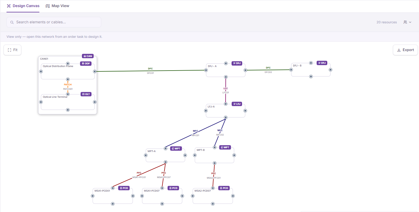
A canvas that works the way designers think
Network designs are rarely created in one pass. Engineers explore options, move elements, reorganize sections and add detail as decisions become available.
A designer can select an eligible network element, place it on the canvas and arrange it using familiar drag-and-drop interactions. Elements can be moved, grouped and positioned to make a large topology easier to understand. The layout can evolve without changing the network's underlying physical meaning.
Moving an element changes how the design is presented; it does not silently change its site, cabinet position or geographic location. Designers keep visual freedom while physical facts remain deliberate, governed decisions.
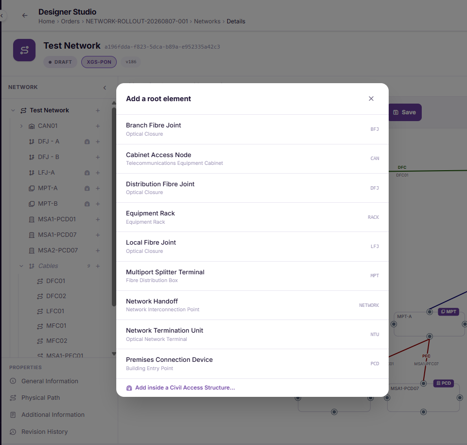
Guided by the catalog, without feeling like a rigid wizard
The available design choices are driven by the Resource Catalog. The catalog describes the roles, specifications, models and relationships that make up a valid telecommunications network architecture.
At the Network root, the platform offers appropriate root elements. When an existing element is selected, choices become more specific: only elements that can be contained, hosted or connected at that point are presented.
The canvas therefore feels open and visual while remaining grounded in the operator's approved catalog. As the catalog grows, the same experience can guide new equipment and network architectures without hardcoded symbol logic.
Connectivity that represents more than a line
On a conventional drawing, almost any two symbols can be joined with a line. In a governed PNI design, a connection must mean something.
Urbbit progressively guides cable creation. After an A-end element is selected, the platform narrows the possible Z-end elements and compatible cable specifications, presenting relevant choices from the catalog and current network.
Detailed termination can be added as the design matures. Ports, fibre ends, material configuration and cable occupancy can be validated by their owning services. Early design stays fast, while later stages introduce the precision required for planning, construction and handover.
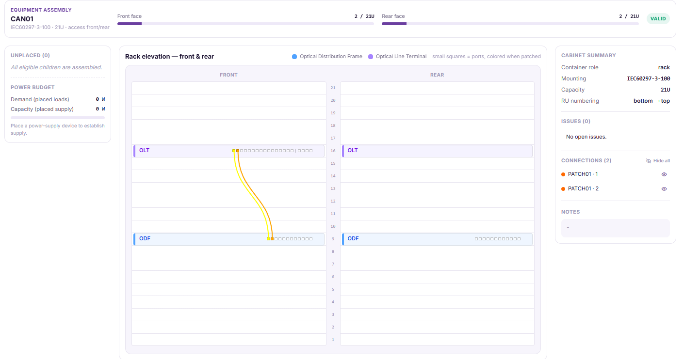
The graph behind the canvas
What users see is a visual design. What the platform maintains is a connected network model.
Two graphs, one governed model
- The catalog graph describes what may be built by connecting resource roles, specifications, models and compatibility rules.
- The network graph describes what the designer has built: stable element nodes connected by governed containment and connectivity relationships.
The position of a box is not its identity, and a visible line is not the sole record of connectivity. Stable identities let the platform distinguish visual layout, equipment containment and physical connection.
Important design commands are checked against the current catalog and latest network state. This can prevent incompatible endpoints, invalid containment, duplicate use of a physical connection point, or references to elements no longer in the design. The user works with familiar network objects while the platform protects their relationships.
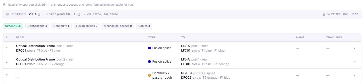
Visual freedom without losing control
Canvas layout and physical topology change for different reasons, so Urbbit manages them separately. A designer may move a group to improve readability without triggering a topology change. When a physical relationship changes, the platform validates and versions that engineering information.
The same principle supports collaboration. Design activity can retain who made a change, when it was made and the work context. Published revisions can become immutable reference points for review, approval and downstream execution.
From logical design to geographic understanding
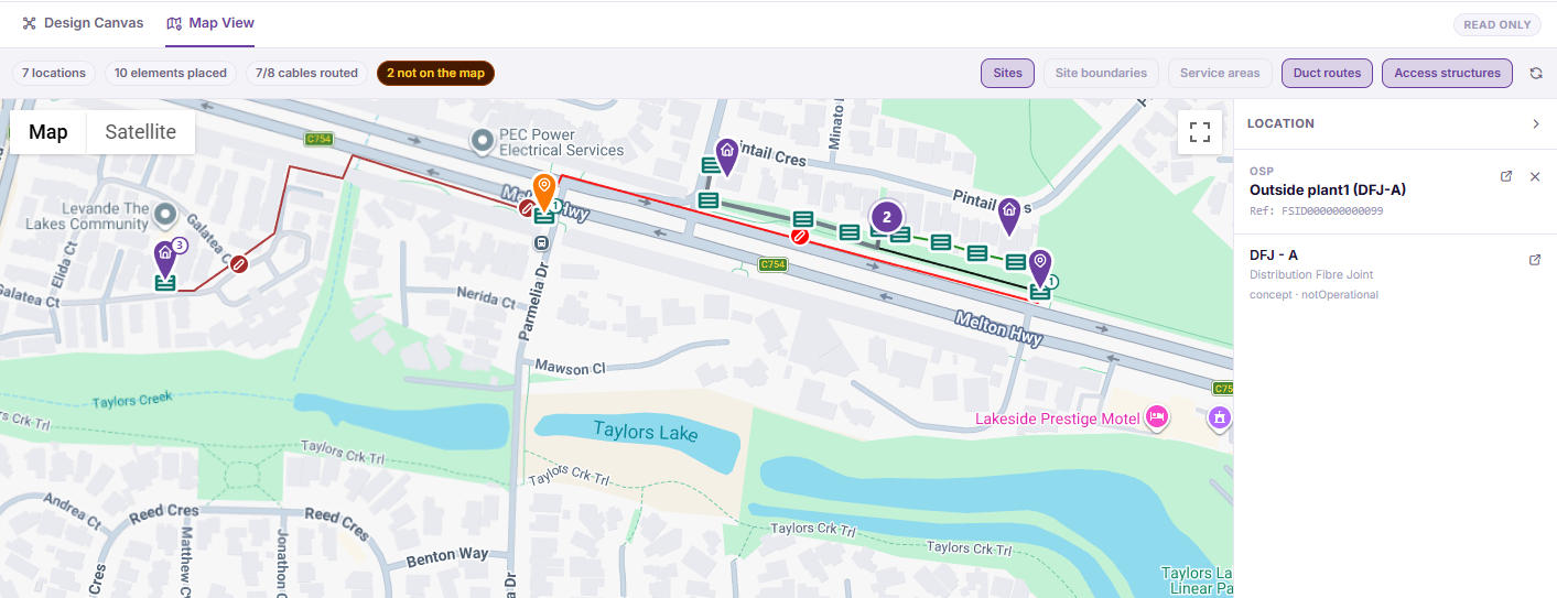
The canvas explains how the network is logically composed and connected. The Network Map explains where it exists.
Both views are projections of the same governed Network. Sites, service areas, civil access structures and duct routes provide geographic context, while the logical canvas remains focused on topology and composition. A cable can follow a real civil route without copying that route into the drawing.
A design that can continue through the lifecycle
Because the design is catalog-driven and graph-backed, it can support the activities that follow:
- design validation and approval
- material and capacity planning
- civil-route and fibre-detail development
- construction work generation
- capture of the as-built network
- reconciliation into Physical Resource Inventory
The design does not need to be discarded and recreated as inventory. It can be progressively enriched, validated and carried forward with its catalog identity and design lineage intact.
Flexibility on the surface, integrity underneath
Urbbit's PNI Network Designer is intended to feel direct: choose an element, place it, arrange the design and build connectivity step by step. Underneath, the catalog guides what is possible and the graph preserves what every relationship means. This balance gives telecommunications teams the freedom to design visually while building a dependable digital representation of the physical network from the beginning.
- Platform Updates
Want to see it on your network?
We will walk you through the designer with your own topology, and be straight with you about the fit.